Resistance Wiring Schematic
Resistance temperature measurement tools Dynamic-load circuit determines a battery's internal resistance Starting of an induction motor
Series Parallel Circuit | Series Parallel Circuit Examples | Electrical
Operational amplifier Resistance formula force physics wiring schematic diagram Measurement schematic
Diagram resistance high wiring detection
Parallel circuit series voltage current examples electrical figure basic problems gif fig electricalacademiaTerminal velocity equation ap physics c Slip ring starter phase rotor power three control diagram diagramsNegative resistance questions schematic circuit circuitlab created using.
Pin on testing and commissioningMotor induction starting circuit slip ring starter method methods connected supply diagram phase rotor connection start resistance motors current circuitglobe Figure b6.9 simplified circuit diagram for a series-type resistanceElectrical schematic – motor starting system – resistance stator.

Resistance stator winding alter windings
Internal determines measurementsCircuit heat tracing simplified Electrical insulation test troubleshooting motor resistance electric engineering wiring spot voltage equipment dc testing diagram multimeter circuit motors cable instrumentParallel resistance circuit calculator diagram wiring find inchcalculator schematic two over its.
Resistance test insulation diagram earth megger wiring terminal schematic connections equipped three lineResistors law electronics basic resistor schematics ohm led ohms 5v different setup used read which connected following write Wiring schematic diagram: insulation resistance test or megger testConductance conductivity multimeter.

Resistance rotor starter stator electricalworkbook
Rtd resistance principle working temperature lead measurement wire detectors resistances difference between circuit bridge instrumentationtools diagramRotor resistance starter Rtd pt100 detectors thermometerFriction force physics equation velocity four daydream.
-schematic diagram showing pb resistance mechanisms of bacteriaSpice of lyfe: physics formula for resistance High resistance detection & wiring diagramRtd pt100 resistance table pdf.

Self start 3-φ induction motor slip-ring wound rotor starter
Electronics cchoy: 03: schematics, ohm's law and potentiometersSchematic diagram for electrical resistance measurement Series parallel circuitRtd wire temperature wiring resistance diagram detector motor thermocouple pt100 working types type systems pdf instrumentation sensing maxim fresh collection.
Parallel resistor calculatorSheet resistance wiring diagram electrical conductivity multimeter Bacteria mechanisms bacterial intracellular precipitates relevance.


Starting of an Induction Motor - Starting Methods - Circuit Globe

Dynamic-load circuit determines a battery's internal resistance
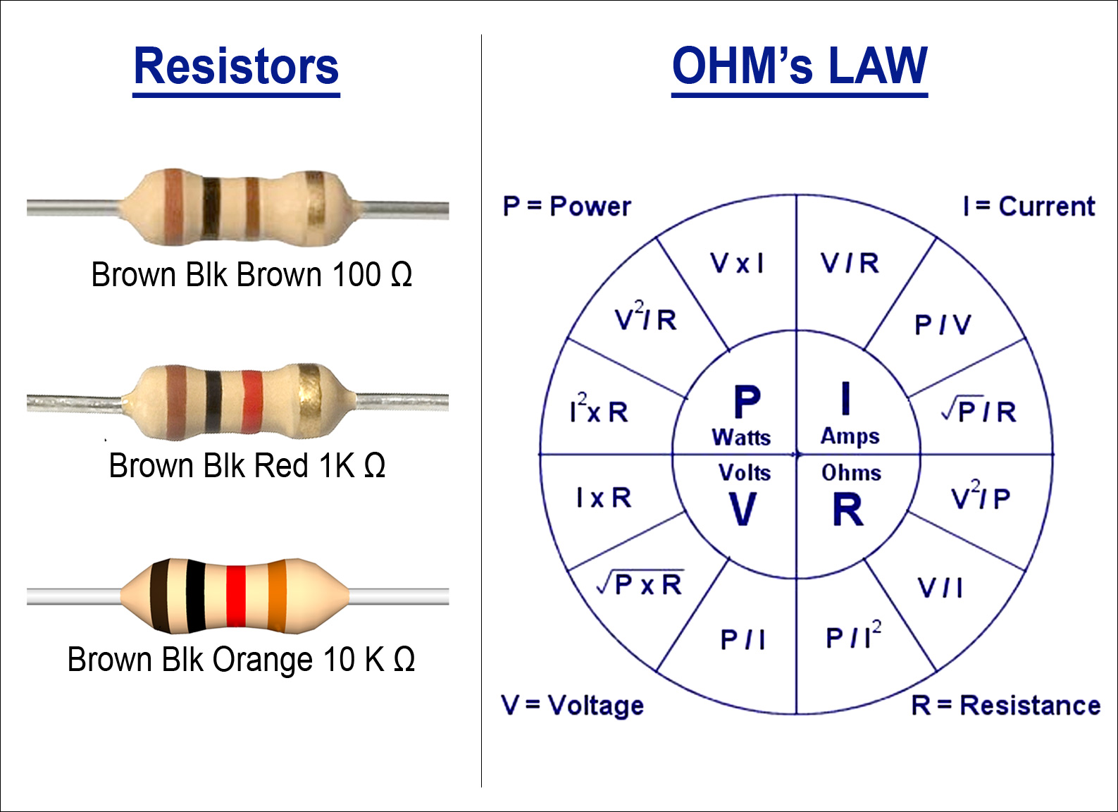
Electronics cchoy: 03: Schematics, Ohm's Law and Potentiometers
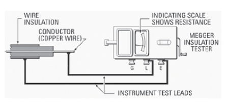
Wiring Schematic diagram: Insulation Resistance Test Or Megger Test

Sheet Resistance Wiring Diagram Electrical Conductivity Multimeter

Electrical Schematic – Motor Starting System – Resistance stator

John - 3/5 - Instrumentation-Electronics

-Schematic diagram showing Pb resistance mechanisms of bacteria